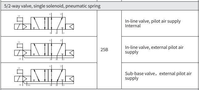
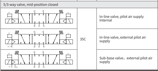
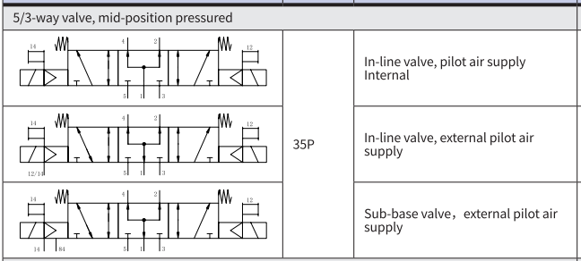
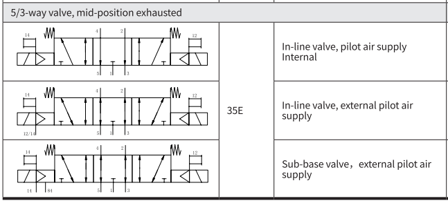
Solenoid valves VMDA-L10 and VMDA-S10, tubular valves M5
| Main technical parameters |
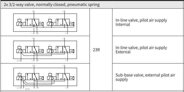
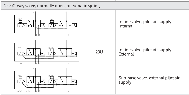
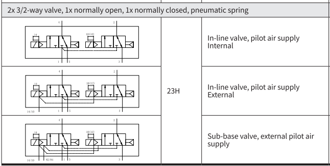
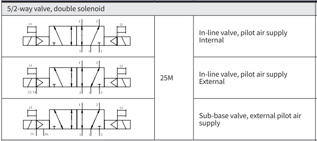
| Valve function | 23R | 23U | 23H | 25M | 25B | 35C | 35P | 35E |
| Steady state position | Monostable state | Bistable state | Monostable state |
| Gas reduction | is | is | - | no |
| Spring return | no | no | - | is |
| Vacuum operation, connect air port 1 | no | Out-of-band pilot gas source |
| Structural characteristics | Piston slide valve |
| Sealing principle | Soft seal |
| Driving mode | Electric drive |
| Control mode | Pilot control |
| Pilot gas source | Inner leader |
| Exhaust function | throttling |
| Manual device | Push-button strap lock |
| Installation mode | Can pass through hole 1) or air path plate |
| Installation position | At will |
| Signal status display | LED |
| Nominal diameter [mm] | 2.7 | 3.2 | 3.2 |
| Standard rated flow [l/min] | 150 | 220 | 210 |
| Flow rate on air circuit plate [l/min] | 150 | 220 | 210 |
| On/off time [ms] | 6/16 | 7/19 | - | 10/30 |
| On/off conversion time [ms] |
| 7 | 15 |
Note 1) If the valves are screwed together to form a valve group through a through-hole, ensure a minimum distance of 0.3 mm by placing spacers between the valves.
Solenoid valves VMDA-L14 and VMDA-S14, tubular valves G1/8
| Main technical parameters |
| Valve function | 23R | 23U | 23H | 23VR | 23VU | 23VH | 25M | 25B | 25A | 35C | 35P | 35E |
| Steady state position | Monostable state | Bistable state | Monostable state |
| Gas reduction | is | no | Yes. | - | no | no |
| Spring return | no | is | no | - | is | is |
| Vacuum operation, connect air port 1 | no | Out-of-band pilot gas source |
| Structural characteristics | Piston slide valve |
| Sealing principle | Soft seal |
| Driving mode | Electric drive |
| Control mode | Pilot control |
| Pilot gas source | Internal leader or external leader |
| Exhaust function | throttling |
| Manual device | Button with lock type |
| Installation mode | Can pass through hole 1) or air path plate |
| Installation position | At will |
| Nominal diameter [mm] | 4.6 | 4.3 | 5.6 |
| Standard rated flow [l/min] | 520 | 520 | 520 | 520 | 520 | 520 | 530 | 500 | 530 | 500 |
| Flow rate on air circuit plate [l/min] | 500 | 500 | 500 | 500 | 500 | 500 |
| On/off time [ms] | 9/25 | 12/18 | 14/22 | - | 13/37 | 12/40 |
| On/off conversion time [ms] | - | 8 | - | 14 |
| specification [mm] | 14 |
| port | 1, 2, 3, 4, 5 | G1/8 |
| 12/14 | M5 |
Note 1) If the valves are screwed together to form a valve group through a through-hole, ensure a minimum distance of 0.3 mm by placing spacers between the valves.
Solenoid valves VMDA-L18 and VMDA-S18, tubular valves G1/4
| Main technical parameters |
| Valve function | 23R | 23U | 23H | 23VR | 23VU | 23VH | 25M | 25B | 25A | 35C | 35P | 35E |
| Steady state position | Monostable state | Bistable state | Monostable state |
| Gas reduction | is | no | is | - | no | no |
| Spring return | no | is | no | - | is | is |
| Vacuum operation, connect air port 1 | no | Out-of-band pilot gas source |
| Structural characteristics | Piston slide valve |
| Sealing principle | Soft seal |
| Driving mode | Electric drive |
| Control mode | Pilot control |
| Pilot gas source | Internal leader or external leader |
| Exhaust function | throttling |
| Manual device | push-button |
| Installation mode | Can pass through hole 1) or air path plate |
| Installation position | At will |
| Nominal diameter [mm] | 5.7 | 6.9 | 7.3 | 6.9 | 6.5 | 6.3 |
| Standard rated flow [l/min] | 850 | 850 | 850 | 850 | 850 | 850 | 1000 | 1000 | 1000 | 950 | 950 | 950 |
| Flow rate on air circuit plate [l/min] | 850 | 850 | 850 | 850 | 850 | 850 | 1000 | 1000 | 1000 | 950 | 950 | 950 |
| On/off time [ms] | 15/40 | 15/48 | 22/32 | 13/50 | 15/48 |
| On/off conversion time [ms] | - | 15 | - | 31 |
| Specification [mm] | 18 |
| port | 1,2,3,4,5 | G1/4 |
| 12/14 | M5 |
Note 1) If the valves are screwed together to form a valve group through a through hole, ensure a minimum distance of 0.2 mm by placing spacers between the valves.
Solenoid valve VMDA-B10, Plate valve M5
| Main technical parameters |
| Valve function | 23R | 23U | 23H | 25M | 25B | 35C | 35P | 35E |
| Steady state position | Monostable state | Bistable state | Monostable state |
| Gas reduction | is | is | - | no |
| Spring return | no | no | - | is |
| Vacuum operation, connect air port 1 | no | Out-of-band pilot gas source |
| Structural characteristics | Piston slide valve |
| Sealing principle | Soft seal |
| Driving mode | Electric drive |
| Control mode | Pilot control |
| Pilot gas source | Internal leader or external leader |
| Exhaust function | throttling |
| Manual device | push-button |
| Installation mode | It can be passed through 1) or air path plate |
| Installation position | At will |
| Nominal diameter [mm] | 2.7 | 1.8 | 1.7 | 4 | 6.5 | 6.3 |
| Standard rated flow [l/min] | 170 | 150 | 140 | 330 | 950 | 950 | 950 |
| Flow rate on air circuit plate [l/min] | 150 | 130 | 120 | 210 | 950 | 950 | 950 |
| On/off time [ms] | 6/16 | 8/11 | 7/19 | - | 8/24 | 11/30 |
| On/off conversion time [ms] | - | 7 | 14 |
| Specification [mm] | 10 |
| port | 1,3,5 | G1/8 is located on the air path plate |
| 2, 4 | M5 is located on the air path plate |
| 12/14, or 84 | M5 is located on the air path plate |
Note 1) If the valves are screwed together to form a valve group through a through-hole, ensure a minimum distance of 0.3 mm by placing spacers between the valves.
Solenoid valve VMDA-B14, Plate valve G1/8
| Main technical parameters |
| Valve function | 23R | 23U | 23H | 23VR | 23VU | 23VH | 25M | 25B | 25A | 35C | 35P | 35E |
| Steady state position | Monostable state | Bistable state | Monostable state |
| Gas reduction | is | no | is | - | no | no |
| Spring return | no | is | no | - | is | is |
| Vacuum operation, connect air port 1 | no | Out-of-band pilot gas source |
| Structural characteristics | Piston slide valve |
| Sealing principle | Soft seal |
| Driving mode | Electric drive |
| Control mode | Pilot control |
| Pilot gas source | Internal leader or external leader |
| Exhaust function | throttling |
| Manual device | push-button |
| Installation mode | Can pass through hole 1) or air path plate |
| Installation position | At will |
| Nominal diameter [mm] | 4.6 | 6.9 | 7.3 | 6.9 | 6.5 | 6.3 |
| Standard rated flow [l/min] | 520 | 520 | 520 | 520 | 520 | 520 | 530 | 500 | 530 | 500 |
| Flow rate on air circuit plate [l/min] | 500 | 500 | 500 | 500 | 500 | 500 |
| On/off time [ms] | 8/23 | 15/11 | 14/22 | - | 13/40 | 12/40 |
| On/off conversion time [ms] | - | 8 | 20 |
| Specification [mm] | fourteen |
| port | 1,3,5 | G1/4 is located on the air path plate |
| 2, 4 | G1/8 is located on the air path plate |
12/14, or 84 | M5 is located on the air path plate |
Solenoid valve VMDA-B18, Plate valve G1/4
| Main technical parameters |
| Valve function | 23R | 23U | 23H | 23VR | 23VU | 23VH | 25M | 25B | 25A | 35C | 35P | 35E |
| Steady state position | Monostable state | Bistable state | Monostable state |
| Gas reduction | is | no | is | - | no | no |
| Spring return | no | is | no | - | is | is |
| Vacuum operation, connect air port 1 | no | Out-of-band pilot gas source |
| Structural characteristics | Piston slide valve |
| Sealing principle | Soft seal |
| Driving mode | Electric drive |
| Control mode | Pilot control |
| Pilot gas source | Internal leader or external leader |
| Exhaust function | throttling |
| Manual device | push-button |
| Installation mode | Can it go through the hole? 1) or gas path plate |
| Installation position | At will |
| Nominal diameter [mm] | 5.7 | 6.9 | 7.3 | 6.9 | 6.5 |
| Standard rated flow [l/min] | 850 | 850 | 850 | 850 | 850 | 850 | 1000 | 1000 | 100 | 950 | 950 | 950 |
| Flow rate on air circuit plate [l/min] | 800 | 800 | 800 | 800 | 800 | 800 | 950 | 950 | 950 | 900 | 900 | 900 |
| On/off time [ms] | 15/40 | 15/48 | 22/32 | 13/50 | 15/48 |
| On/off conversion time [ms] | - | 15 | - | 31 |
| Specification [mm] | 18 |
| port | 1,3,5 | G3/8 is located on the air circuit board |
| 2, 4 | G1/4 is located on the air path plate |
| 12/14, or 84 | M5 is located on the air path plate |

Precautions for installation and use of solenoid valves
Although the directional valve can be installed in any direction, the vibration of the device or the flow of condensed water, oil, and other liquids to the coil of the solenoid valve can cause the directional valve to malfunction. Therefore, attention should be paid to:
01 Avoid the impact of vibration on the solenoid valve slide. During installation, the vibration direction can be at right angles to the action direction (axial) of the solenoid valve slide column to avoid the impact of vibration on the solenoid valve slide column.
To prevent condensate, oil, etc. from flowing into the coil of the solenoid valve, it is best to install the coil facing upwards or horizontally.
Before installation, dust, oil stains, debris, and other debris particles in the pipeline should be blown clean to avoid affecting the operation and damage of the valve.
The inlet of the 04 internal pilot solenoid valve should not be throttled to prevent misoperation due to excessive pressure drop during reversing.
Install the 05 directional valve as close to the cylinder as possible: firstly, reduce air consumption, and secondly, respond quickly.
Please insert the tubing in place and confirm that it cannot be removed before use.
Although the coil calibration of our company's product is 100% ED, prolonged electrification can cause overheating, leading to insulation deterioration and energy loss. In the case of prolonged continuous power on, it is advisable to consider using solenoid valves with memory function to shorten the power on time, extend the service life of the coil, and save energy consumption.
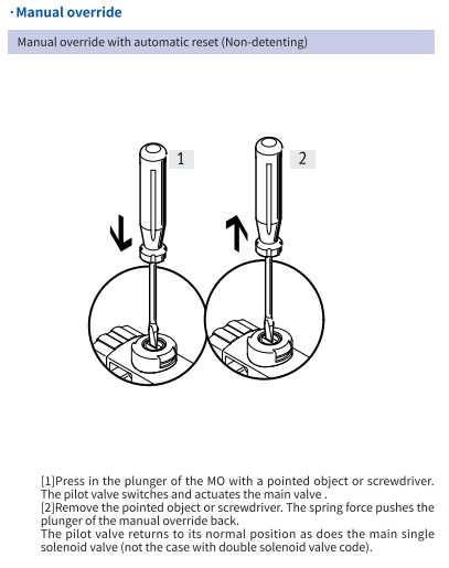
Manual buttons should not be used when the 08 solenoid valve is energized.
The operating voltage of the 09 solenoid valve should be within the specified voltage range to avoid poor valve operation or burning of the coil.
The 10 electric solenoid valve is installed in the control cabinet. When powered on for a long time, attention should be paid to the ventilation and heat dissipation of the control cabinet to ensure that the temperature inside the cabinet is within the safe temperature range of the solenoid valve;
To prevent the simultaneous energization of two coils of the dual electric control solenoid valve, the control circuit should be designed with interlocking protection control circuit.
The breathing hole at the internal control piston of the 12 main valve and the exhaust port of the pilot valve should not be blocked or the exhaust should not be smooth
13 DC specification solenoid valves have polarity indicator lights, so when wiring, pay attention to the positive and negative poles. "1" should be connected to the positive pole, and "2" should be connected to the negative pole. If the connection is reversed, the indicator light will not light up and the valve can still operate.


 PDF
PDF
